Building a Single Board Computer Around the MOS 6502
After watching several repair videos about Commodore 64s, Nintendos, and other 8-bit era computers, I came to the conclusion that it can’t be that hard to make one, right? Here’s my process from concept to prototype!
Breadboarding
I began by starting to breadboard all of the components I wished to use. In my case, that was a Rockwell 6502 CPU, 32KB of ROM, and a 20x4 Character LCD. However, the complexity of having all of these on a breadboard skyrocketed and debugging was extremely difficult (I did this in 2019 and didn’t have a logic analyzer until 2021!). Regardless, here was the set-up I was going for.

It was very messy. I did my best to keep notes of what I was doing as well as labeling bus rails where I could, but when something went wrong, it was difficult to know why. And go wrong it did. After all of this work and meticulous wire routing, I gave up on the breadboard. I couldn’t get the LCD even initialized from the 6502. Maybe it was the unstable clock source (I was having some issues with using a crystal) or maybe it was just all the interference from the big spiky breadboard rails, or maybe I really was just coding it wrong. Keep in mind, every time I wanted to change the ROM, I had to pull it out of the breadboard and flash it with my TL866 programmer, and trying to do that without disturbing any of the wires wasn’t easy. And that was the last straw, I wanted to step it up and prototype with my own PCB instead.
Schematic and Layout
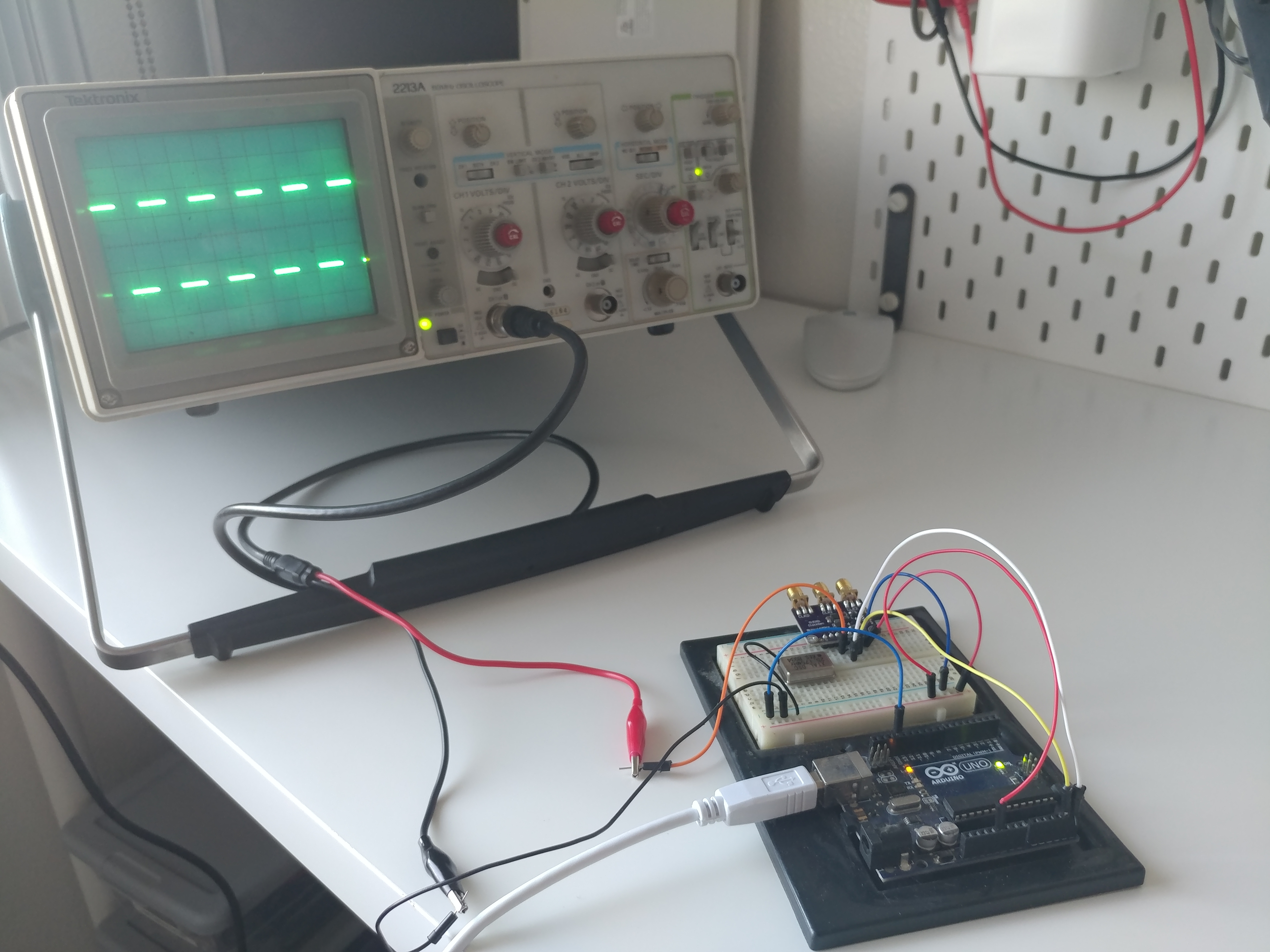
Because I didn’t yet have a working breadboard layout, I designed my circuit around the ability to easily prototype rather than to make a final device. Thus, I wanted just the bare minimum of the 6502, 32K ROM, 8K RAM, the LCD pins, reset circuitry, a power header, and ample open databus connections to attach wires to. Additionally, I wanted to use an external clock source, since I still wasn’t entirely sure if the crystal I was using was even a good enough clock for the 6502. I had been doing some experimenting with an Arduino Uno controlling an I2C clock generator and that appeared to be much more stable than the crystal. Or, at the very least, I found the square waves to be much sharper even up to 25MHz:
Lastly, I also needed an address decoder. Because I was still figuring that out, I wanted that to be external as well. In any case, my needs were decided and I set out to create a schematic. I had heard good things about JLCPCB and EasyEDA from a friend, so I went with their software. It was, in fact, easy. I plopped the components I needed onto the schematic, connected each pin to a net, and that was that. Here’s what I came up with (full pdf available):
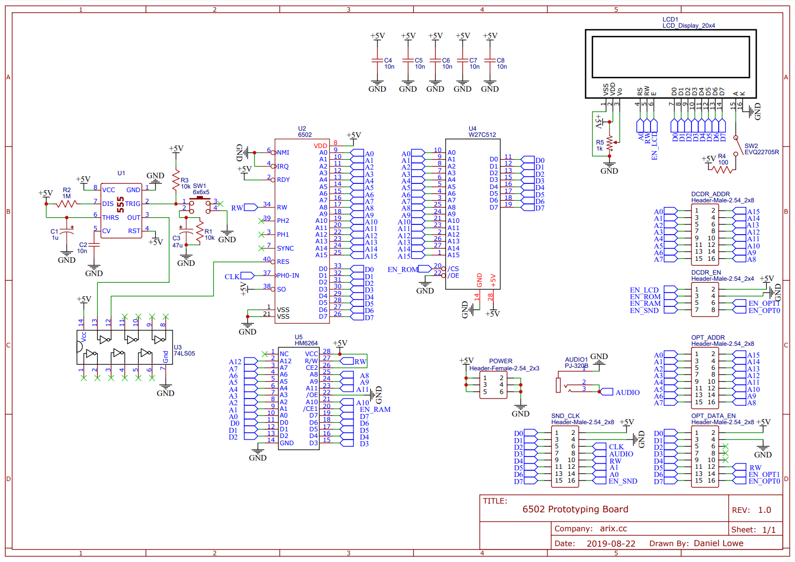
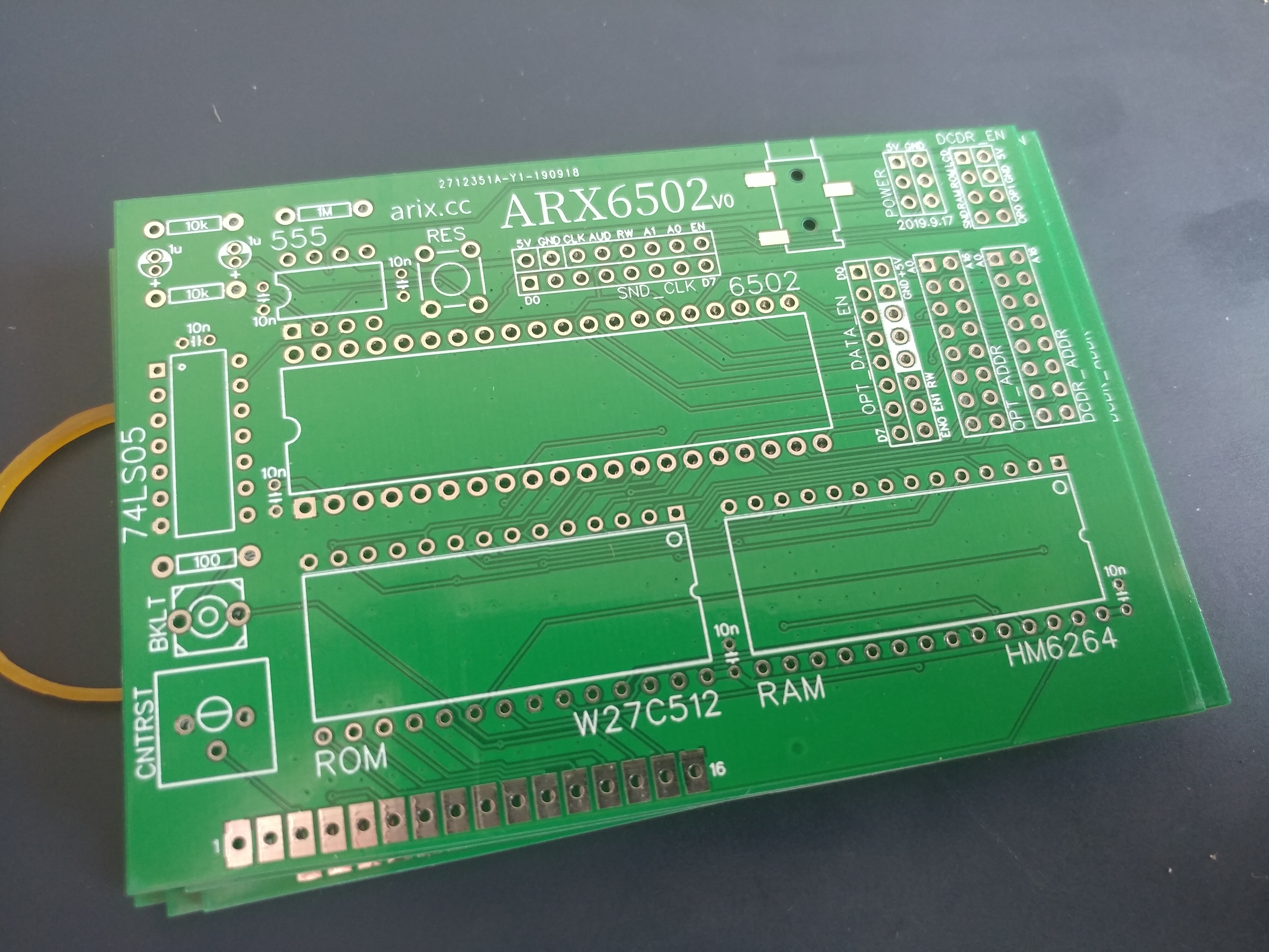
It doesn’t look like much but I was pretty sure this was everything I needed, so, I began laying everything out on a PCB. It was a bit of a learning curve at first but I think I did an acceptable job for my first time. I hadn’t taken any formal EE classes at the time, pretty much all of my PCB knowledge was from watching Dave Jones at the EEVBlog. In any case, I came up with the following layout:
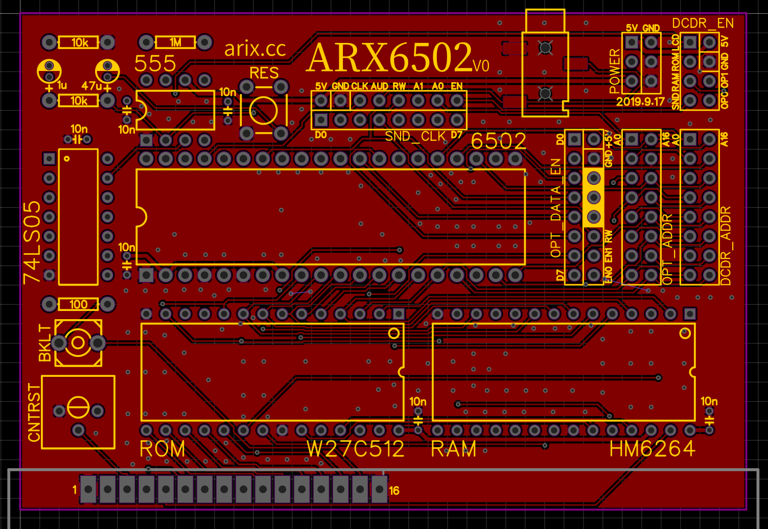
Top Layer
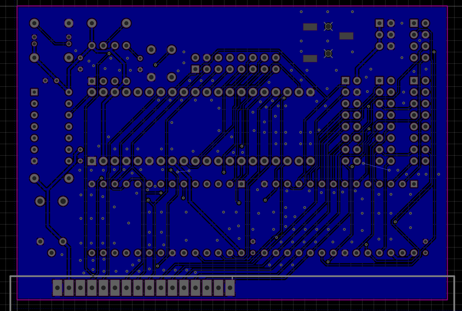
Bottom Layer
While I didn’t know much at the time, the two rules I remember following closely were to use plenty of ground-plane stitching as well as use as few right-angle traces as possible (prefer 45 degree or below). In any case, I ordered and populated the board!
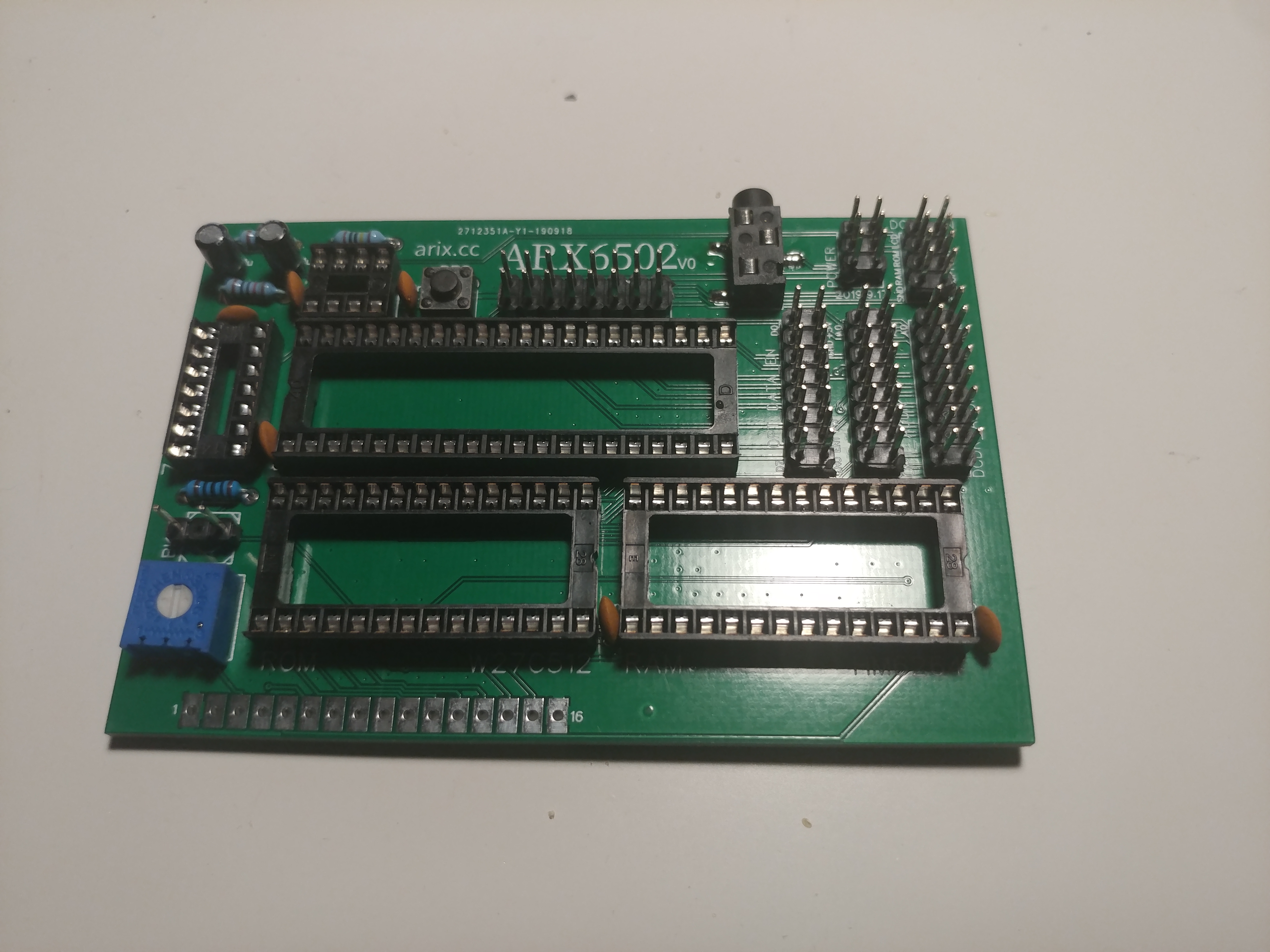
Testing
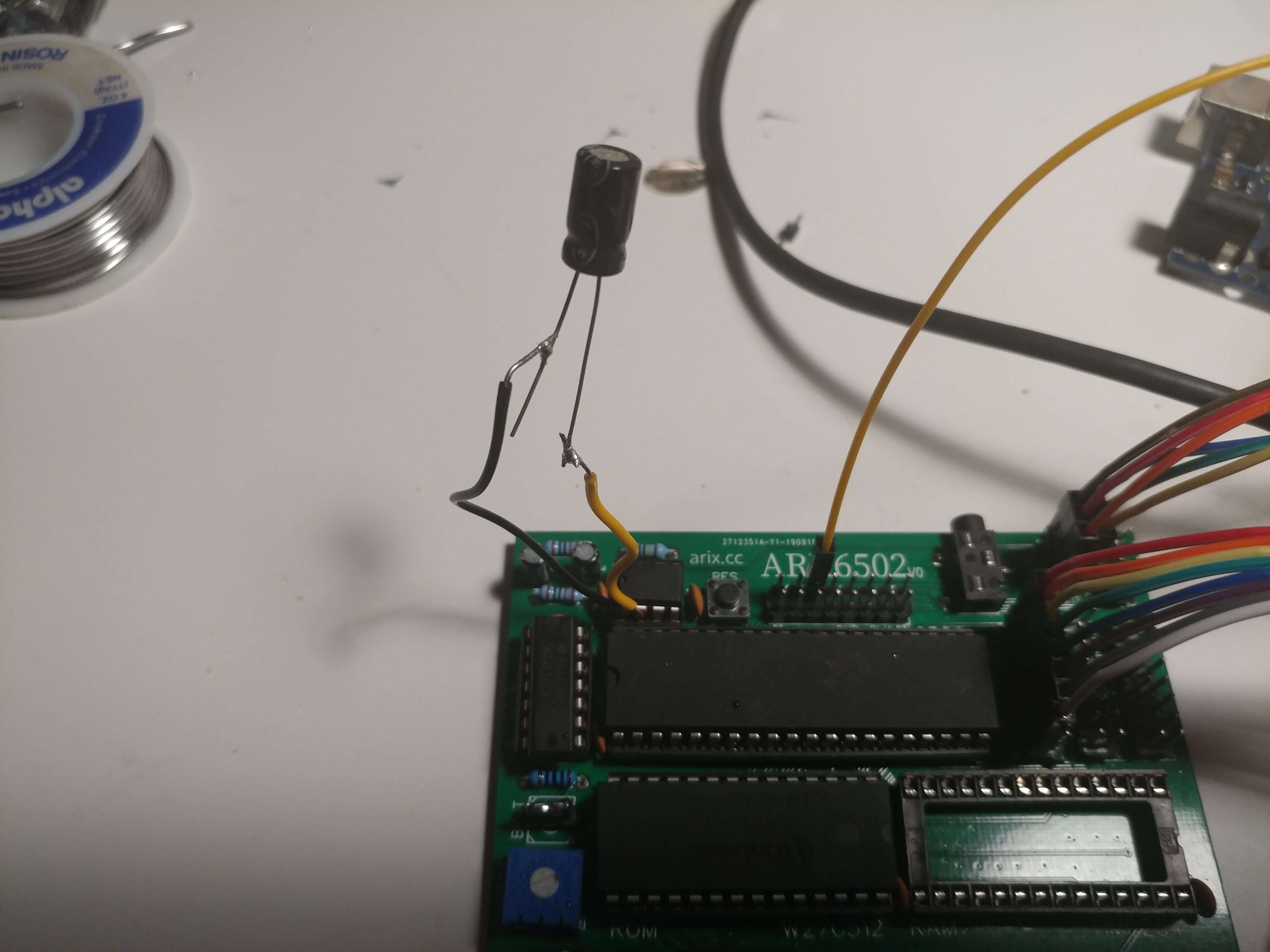
Everything was fitting well so far. And, next, it was time to actually begin testing. The first section of my PCB I had trouble with was the reset circuitry. I was using a 555 timer with some capacitors, resistors, and a NOT gate to invert and trigger the active-low reset pin on the CPU. For whatever reason, it only worked sometimes, and I eventually realized this was a matter of it triggering too quickly, so I used a larger value of capacitor than planned. The testing, though, looked a bit ugly…
Oh well, I thought, this is why I wanted a prototype board before trying to design a final one. Aside from that, everything went amazingly smoothly. I used the assembly code I had written for the breadboard test to try to test this version, and…
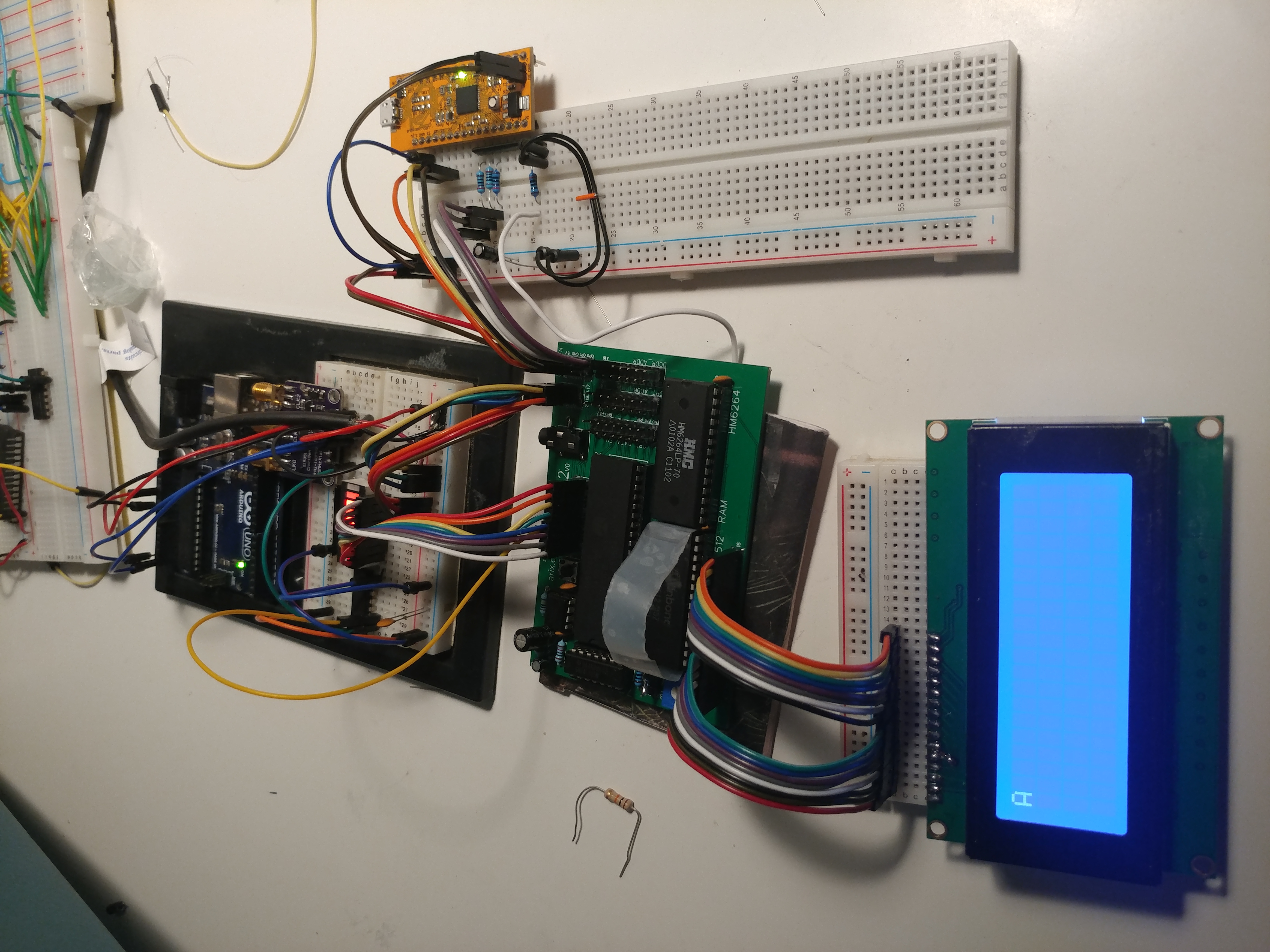
It worked!! I was able to initialize the LCD and output an ‘A’ character. I should note, I’m skipping over a lot of other development I needed to get here. For example, on the right is an FPGA that I programmed using ICEStudio to do all the address decoding. It’s meant to take the 6502’s address as an input, and output an enable signal to the LCD when it matches a certain value. This would normally be the job of the PLA on a Commodore 64, for example (or discrete TTL on even older machines).
With that much working, I didn’t stop there. I wanted to test even more of what I could do. For no reason at all (truly, for no reason), I connected two screens and added a little bit more significant output. Here’s a link to the assembly code used here, if you’re so inclined.
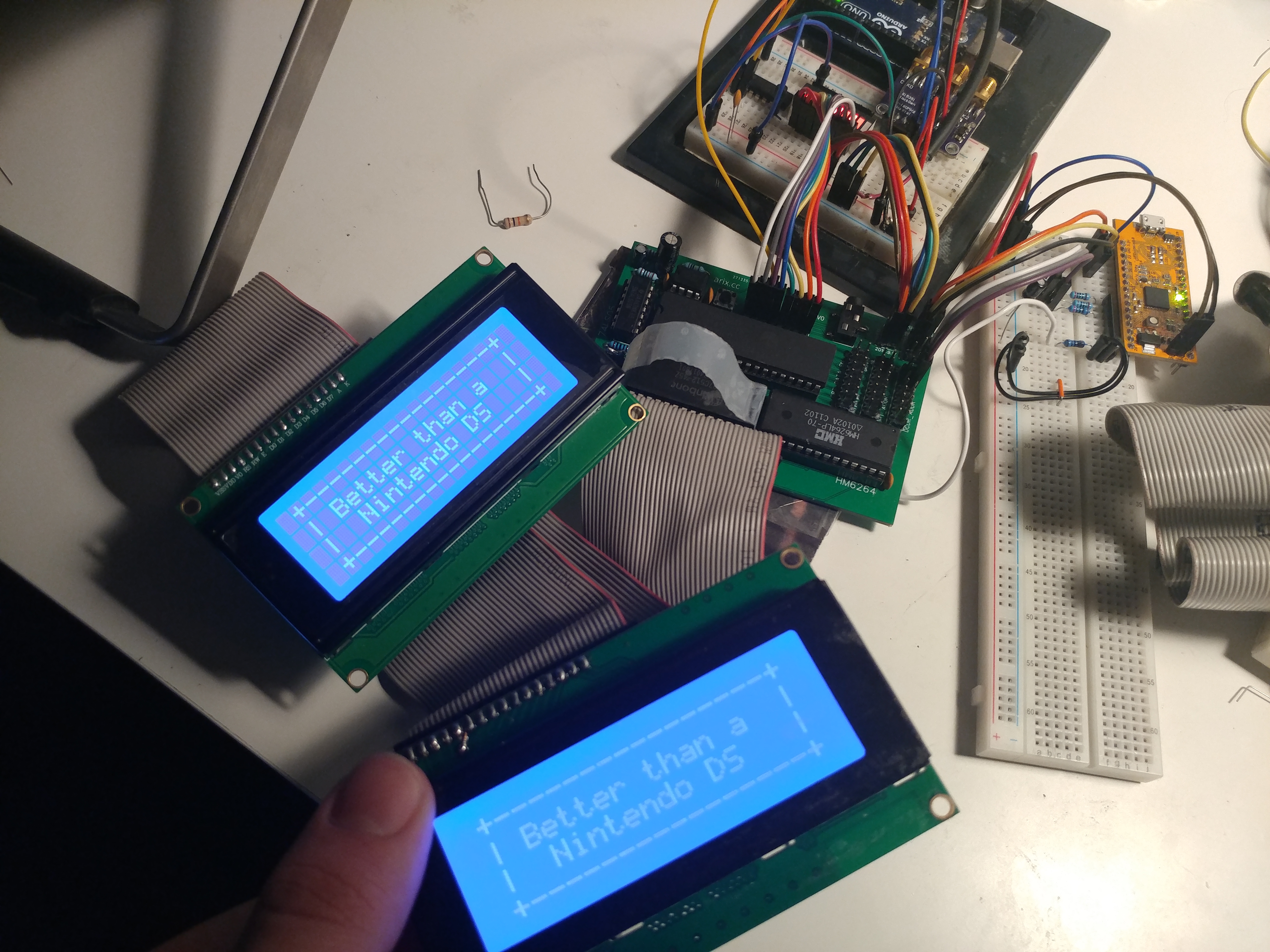
Silliness and jokes aside, my next step was to get some form of input working. I was hoping to use a PS/2 keyboard, but after reading the documentation for it, I didn’t have the components needed. So, I went a little bit simpler. I wired up 6 buttons to a tri-state buffer and added another line from the FPGA address decoder to enable the buffer at a different address than the LCD. And, after wiring the buffer to the databus, I was able to read from them! As before, here is the assembly code for this test as well.
You’ll note that I also took a little bit of time to clean up the wiring here and minimize as I was working. After this point, I ran out of time and ideas and didn’t end up continuing the project any further. Now that I’m just about to graduate though, I’m definitely considering working on this some more and hopefully making a board that has everything I need, possibly even a controller? A gameboy-like system would be pretty neat! In any case, that’s all I have to show, thanks for reading!