<?xml version="1.0" encoding="utf-8"?><feed xmlns="http://www.w3.org/2005/Atom" ><generator uri="https://jekyllrb.com/" version="4.2.1">Jekyll</generator><link href="/feed.xml" rel="self" type="application/atom+xml" /><link href="/" rel="alternate" type="text/html" /><updated>2026-08-09T05:18:59+00:00</updated><id>/feed.xml</id><entry><title type="html">Coding Tetris from Scratch on an AVR Microcontroller</title><link href="/hardware/2021/06/09/avr-tetris.html" rel="alternate" type="text/html" title="Coding Tetris from Scratch on an AVR Microcontroller" /><published>2021-06-09T00:00:00+00:00</published><updated>2021-06-09T00:00:00+00:00</updated><id>/hardware/2021/06/09/avr-tetris</id><content type="html" xml:base="/hardware/2021/06/09/avr-tetris.html"><![CDATA[<p>For the final project in Professor Tony Givargis’ embedded systems course, we were given the vague task to “do something interesting.” So, I made a version of Tetris on an ATMEGA32.</p>

<hr />

<p>For all previous projects, we had only used a 20x4 character LCD and a 4x4 matrix keypad for human interface. This was the first thing I wanted to change. Instead of a boring character LCD, I decided to instead use a 128x64 dot-matrix LCD. The communication was very similar (it could even emulate a character LCD) but it allowed for pixel-by-pixel control, which was perfect for Tetris. Second, I decided to scrap the number keypad for a Nintendo NES Controller. This would make it feel more “gamelike,”</p>

<p>Unfortunately, these decisions came with the need to write the drivers from scratch for both the LCD and the controller since I couldn’t use the code I wrote on the last projects, but that was a challenge I was open to facing.</p>

<p>First, the LCD. After reading documentation and understanding how the memory layout is mapped to the screen, I wrote code that would update certain parts of the screen at once. Because the layout is a bit funny, and I wanted to have the screen in portrait rather than landscape, I wrote functions to abstract away the memory arrangement in favor of straightforward X and Y coordinates using some simple math. From there, it was pretty easy to modify pixels on the screen. The only final issue was that I had to modify 16 pixels in a vertical line at once. While I could have made code that read the memory and then updated certain pixels and wrote them back, that seemed inefficient and I decided to instead work around it in my game design, cleverly lining game and block borders up with these 16px lines so that drawing would be much faster.</p>

<p>Next, the Nintendo controller. This was pretty easy, as the controller functions using a parallel-in serial-out shift register. All I needed to do was latch the data, then cycle the clock pin while reading the data pin each time.</p>

<p>Lastly, to put it all together, I had to write the actual game logic. This turned out to be the hardest part, as there are a lot more edge cases in Tetris than I though, especially when it comes to piece rotation and bumping a piece if it would fit somewhere other than its current location when rotated. Regardless, I figured that out as well, and used some randomness created by how long it takes the user to start the game from power on to change the piece set each time. Randomness in embedded systems is incredibly hard to do if you want true random numbers (especially when it comes to cryptography) but for the purposes of a game, this was an acceptable approach to me.</p>

<p>Finally, below is a demonstration of it all working together! Here’s the <a href="https://github.com/ArixZajicek/AVRTetris" target="_blank">C Source Code on GitHub</a> as well.</p>

<iframe width="560" height="315" src="https://www.youtube.com/embed/NKyel5t8xis" title="YouTube video player" frameborder="0" allow="accelerometer; autoplay; clipboard-write; encrypted-media; gyroscope; picture-in-picture" allowfullscreen=""></iframe>

<p>Thank you for reading!</p>]]></content><author><name></name></author><category term="hardware" /><category term="featured" /><category term="microcontrollers" /><category term="embedded systems" /><category term="game" /><category term="avr" /><summary type="html"><![CDATA[For the final project in Professor Tony Givargis’ embedded systems course, we were given the vague task to “do something interesting.” So, I made a version of Tetris on an ATMEGA32.]]></summary></entry><entry><title type="html">Emulating the MOS 6502 Microprocessor with C++</title><link href="/software/2020/09/10/arx65.html" rel="alternate" type="text/html" title="Emulating the MOS 6502 Microprocessor with C++" /><published>2020-09-10T00:00:00+00:00</published><updated>2020-09-10T00:00:00+00:00</updated><id>/software/2020/09/10/arx65</id><content type="html" xml:base="/software/2020/09/10/arx65.html"><![CDATA[<p>This sprung up as I was working on <a href="/hardware/2019/11/11/arx6502.html">ARX6502</a>, my single board computer project. I wanted an easier way to test the software I was writing than having to remove and flash the EEPROM every time I wanted to update the code.</p>

<hr />

<h2 id="requirements">Requirements</h2>

<p>I needed an emulator that was much more modular than anything I found online. Most emulators target specific system but because I was building my own from the ground up, I needed something that could better tailor to that. Thus, I needed to abstract away the peripherals from the CPU. This would create a decrease in speed as the emulated CPU can’t take shortcuts when doing things like writing or reading from memory, but that’s alright because this emulator is focused on accuracy rather than speed.</p>

<p>On that note, my other goal was to make the emulator as accurate as possible to the real CPU. Again, my goal wasn’t to play NES games or anything that required speed, but rather to have an emulation of whatever physical system I was building. Thus, I needed to pay special attention to the CPU’s behavior and timing states.</p>

<p>On the bright side, because I’m not creating a system to support existing code but rather plan to write my own code, I don’t have to implement any of the several undocumented opcodes that get used from time to time in other software.</p>

<h2 id="implementation">Implementation</h2>

<p>As mentioned, I needed a modular system. Thus, the backbone of the system is the databus class. The databus also virtually encapsulates the idea of an address decoder, as modules are given an address range when they are attached and the databus will trigger a write/read to a module only if its within its address range (the equivalent of an “enable” pin). Currently, only the CPU may perform the read or write operations.</p>

<p>The CPU itself is initialized to what a real 6502 would be after reset. It then reads the instruction start address from 0xFFFC and 0xFFFD and into the program counter and begins fetching bytes from the databus to read and process. I won’t go into detail here, but all of the standard opcodes are fully implemented to the best of my knowledge. This includes all mathematical, branching, and other instructions. All flag registers are also set, and special details like how branching instructions may take an extra clock cycle in some situations are also factored for. However, the real difficulty now is that I actually need to test and verify everything actually works.</p>

<p>The problem with this is that I can’t just write a program that “prints” to an output, as there’s no such thing as an output without more hardware. So, I decided to implemented another piece of hardware to do this, the ACIA6551. This is a basic serial IO chip that’s meant to go along with the 6502, and was typically used for terminal displays. Thus, it’s perfect for my application. My main motivation for using this chip is that I can test with software that others have written rather than only ever being able to run my own code.</p>

<p>The ACIA6551 itself is quite simple. I only had to implement reading, writing, waiting, and scanning for data, as well as a handful of registers. Then, I used SDL2 to create a graphics window and made a virtual terminal that’s connected to the ACIA chip. The virtual terminal would display text sent from the program, and would let the user send keystrokes back.</p>

<p>Oh, I almost forgot to mention it because it’s so trivial, but I implemented RAM and ROM modules as well– really it’s just a single module that can have read-only enabled or disabled. This simply has a big array of bytes and will read or write to them from the databus. I also implemented a load routine so that machine code can be loaded into sections of memory.</p>

<h2 id="testing">Testing</h2>

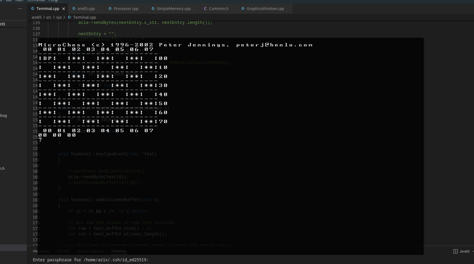
<p>All of that out of the way, I was ready to try a real program as a test! For this, I decided to go with Microchess by Peter Jennings. This is a very simple chess game that was written for the KIM-1, a 6502 based computer that also happened to use an ACIA6551. Thus it was perfect for testing my emulator. And, while there’s definitely an error with my code, it worked enough to see and interact with the program!</p>

<p><img src="/assets/posts/arx65/start.png" alt="The chess game loads!" title="It loads!" /></p>
<p class="img-caption">The chess game loads!!</p>

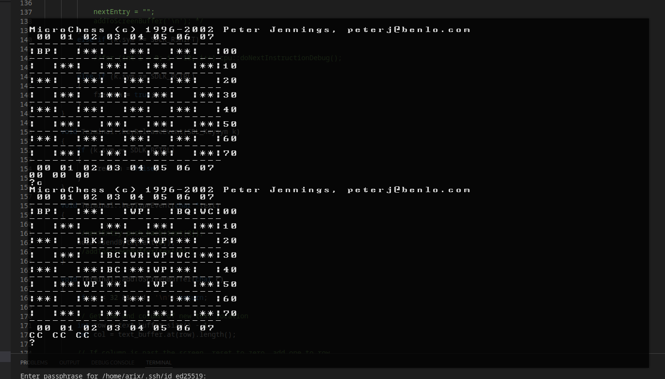
<p><img src="/assets/posts/arx65/c.png" alt="Pushing C begins the game, but the pieces are displayed oddly." title="Uh oh..." /></p>
<p class="img-caption">Pushing C begins the game, but the pieces are displayed in the incorrect places.</p>

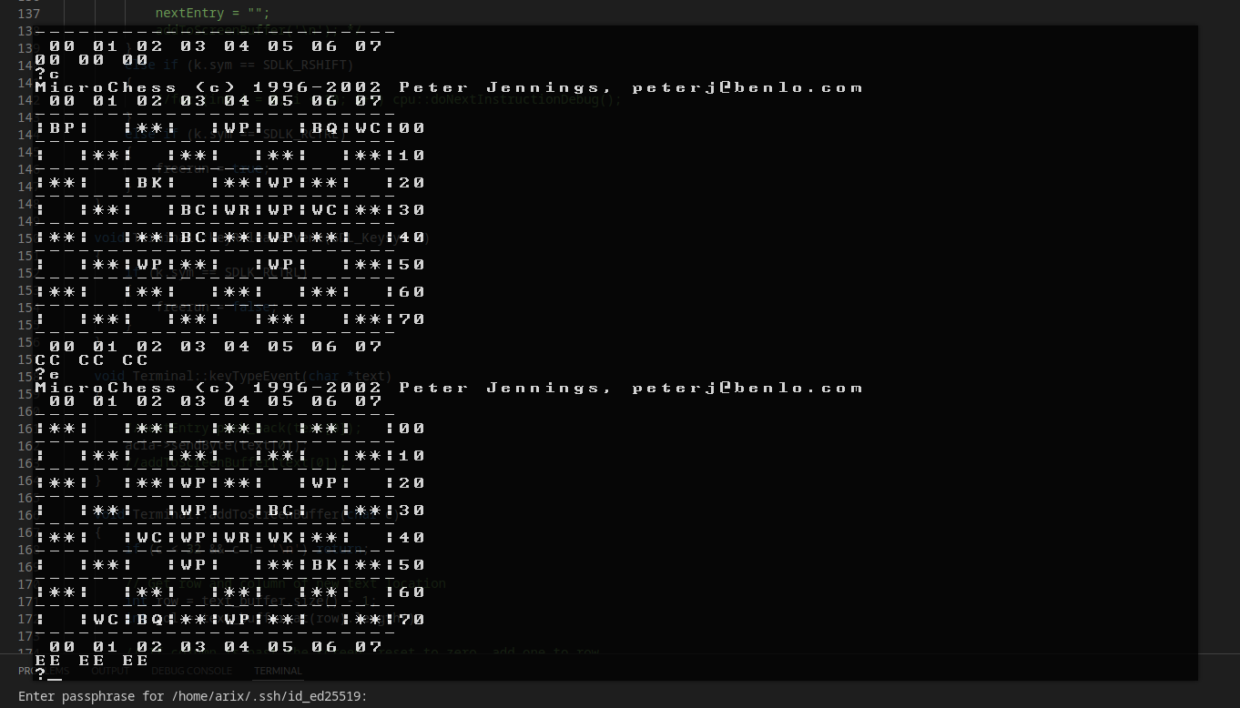
<p><img src="/assets/posts/arx65/e1.png" alt="Pushing E 'flips' the board, but flip is unclear when they aren't showing up." /></p>
<p class="img-caption">Pushing E 'flips' the board, but it's hard to tell what's actually being flipped.</p>

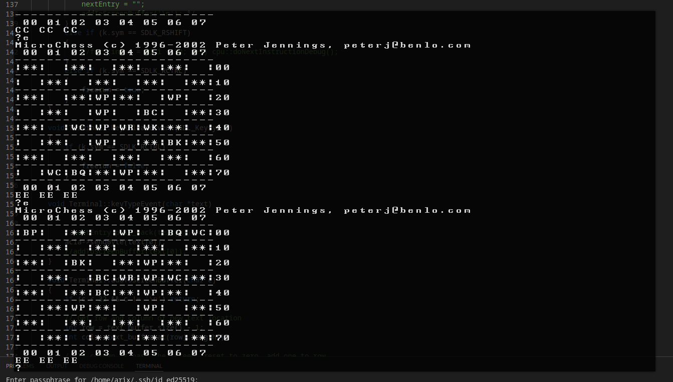
<p><img src="/assets/posts/arx65/e2.png" alt="Pushing E again returns it to the previous broken arrangement." /></p>
<p class="img-caption">At least pushing E to flip the board again returns it to its original broken arrangement...</p>

<p>You can see the chessboard pattern, as well as type commands that actually modify the board. However, there’s definitely an issue somewhere, as the chess pieces are not lined up where they’re supposed to be. For whatever reason, they’re spread in odd places on the board. While this is going to take more debugging, it’s definitely very good progress and I’m happy that this much of the program is running already!</p>

<p>As another test, I did try benchmarking the processor using a bubble sort algorithm and repeating it several times in sequence. However, while the equivalent processor frequency was over 100 MHz (the 6502 typically runs at 2-4MHz), I actually have no idea if that’s good or bad for an emulator that doesn’t have a display attached and is just running standalone. So, I’ll implement more of the system and attempt to compare with emulators like VICE for the C64 or FCEUX for the NES.</p>

<p>If you want to see the source code, I’ve <a href="https://github.com/ArixZajicek/arx65" target="_blank">republished it on GitHub here</a>.</p>

<p>That’s it for now, thanks for reading!</p>]]></content><author><name></name></author><category term="software" /><category term="featured" /><category term="emulation" /><category term="retro" /><summary type="html"><![CDATA[This sprung up as I was working on ARX6502, my single board computer project. I wanted an easier way to test the software I was writing than having to remove and flash the EEPROM every time I wanted to update the code.]]></summary></entry><entry><title type="html">Modding the Creality Ender 3 Pro: Direct Drive</title><link href="/hardware/2020/07/05/ender-3-pro-direct-drive.html" rel="alternate" type="text/html" title="Modding the Creality Ender 3 Pro: Direct Drive" /><published>2020-07-05T00:00:00+00:00</published><updated>2020-07-05T00:00:00+00:00</updated><id>/hardware/2020/07/05/ender-3-pro-direct-drive</id><content type="html" xml:base="/hardware/2020/07/05/ender-3-pro-direct-drive.html"><![CDATA[<p>Get better prints with a direct-drive system!</p>

<hr />

<p>The Ender 3 (and many other printers) use a Bowden tube system. While this is an easy and cost effective method of extrusion, the filament cannot be controlled precisely due to the play of the filament over a long distance. That’s where direct drive extrusion comes in. We reduce the distance between the extrusion motor and the nozzle so that we can control the filament much more precisely. The effect of this becomes even more visible once we start printing at higher speeds. If you’d like to know the specifics and differences of each tube system, I suggest you check out this article by Taylor Landry. They’ve done a great job explaining all there is to know about the two systems.</p>

<p>I should note that while Bowden extruders will theoretically allow the X-axis carriage to move faster because of the decreased weight, they don’t have precise enough control of the filament at higher speeds due to hysteresis and play. Mounting the extruder motor directly on the carriage may decrease the theoretical maximum speed, but better filament control makes up for it greatly.</p>

<p>If you search Thingiverse for Ender 3 direct drive, you’ll find several different approaches. The most popular direct drive option for Ender 3 printers is the SpeedDrive v1 by sashalex007. This project claims to keep the X axis as balanced as possible by mounting the motor on the opposite side of the crossbar as the extrusion head. While this sounds like a good option, mounting the motor here will reduce both your X and Z travel by about 10%, requiring you to make an extension for your limit switch and reducing the overall print area.</p>

<p>The best alternative I could find for the SpeedDrive is the Direct Drivinator, by Madau3D. Instead, this mounts the motor over the crossbar and to the left of the entering filament. This allows us to keep our entire X, Y, and Z range. This option also appears to have the smallest effect on the balance of the X axis since the motor is mounted above the roller bearings, while the SpeedDrive attempts to rebalance the stock carriage by mounting the motor behind the rollers. Because of this, I will be using the Direct Drivenator, but you can use any mount you prefer.</p>

<p>First, we’ll need to print out the mount. The creator of this bracket suggests using 15% gyroid infill, 0.2mm layer height, and supports. This will take about 4-6 hours.</p>

<p>Now, we’ll take off the X axis carriage and extruder motor. Start by removing the belt from the carriage. Remove the Bowden tube and tube retainer from the extrude head. Using a wrench and hex bit, remove the upper roller bolts. Take the metal bearings from these bolts and press fit them into the motor mount. If the fit is too loose, use epoxy to hold them in place. Re-attach the bolts and rollers, now with the mount in place, to the X axis crossbar. Screw the bowden tube retainer back into the extrude head, but do not insert the bowden tube.</p>

<p>Next, we’ll remove the extruder motor from its original bracket. First, unplug the motor. Remove the bowden tube from the retainer. Next, loosen but do not fully remove the tensioner spring. Now, unscrew the hinge of the spring arm and carefully lift it away, taking note that the spring will be under pressure still. Screw the tensioner screw back in fully so that it’s out of the way, and remove the remaining screws from the motor.</p>

<p>The next step is to cut off the correct amount of the bowden tube to use in the new direct drive system. Start by cutting off about 5cm of tube. Insert the tube fully into the retainer on the nozzle, and lower the mount we just removed onto this tube. Make sure the tube is pushed fully into both retainers, and check the holes on the mount we removed to the bracket we printed. If the screw holes do not line up with those on the bracket behind it, cut off pieces of tube slowly until the holes line up. Once the tube is the correct length, insert the motor into the bracket. I angled the connector on the motor backwards so that I don’t see it from the front, but you can angle the connector up too. Reattach the mount to the motor, starting with the bottom and back screws, then attaching the arm, spring, and spring retainer last. You may need to hand loosen the tensioning screw before attaching the spring, as you will not be able to reach a tool under it. Lastly, don’t forget to re-attach the belt underneath the carriage.</p>

<p>Now that the motor is mounted, the last step is to extend the extruder motor cable. Cut 4 lengths of wire about 35cm long. Strip the ends of the wires. Now, one at a time, cut the wires from the extruder connector, and solder on the new wires. I recommend you use heatshrink to insulate the wires, but electrical tape will work too. Note that the middle two connections may be naturally twisted. This is why I recommend to only cut and attach one wire at a time so as to not lose track. Lastly, we connect the motor and use zip ties to route the motor cable and extruder/fan cables together and out of the way.</p>

<p>And, that’s it! I suggest to try a test print to make sure everything is wired up correctly. The benefits may not be obvious yet, but your prints should come out with less blobbing and stringing. This helps a lot with filament control at higher speeds. If you have any questions or trouble, leave a comment below and I’ll see if I can help!</p>]]></content><author><name></name></author><category term="hardware" /><category term="3d printing" /><summary type="html"><![CDATA[Get better prints with a direct-drive system!]]></summary></entry><entry><title type="html">Using Makefiles Effectively</title><link href="/software/2020/04/18/using-makefiles-effectively.html" rel="alternate" type="text/html" title="Using Makefiles Effectively" /><published>2020-04-18T00:00:00+00:00</published><updated>2020-04-18T00:00:00+00:00</updated><id>/software/2020/04/18/using-makefiles-effectively</id><content type="html" xml:base="/software/2020/04/18/using-makefiles-effectively.html"><![CDATA[<p>Other online guides only showed bits and pieces of a decent makefile but ones that were quick to the point were often missing a feature I’d have liked to seen. I figured I’d post and explain my one-and-done solution for efficient compilation.</p>

<h2 id="theory--motivation">Theory &amp; Motivation</h2>

<p>I’ve been working on a modestly sized project for a little while now, and up until now I’ve been using the most ineffective possible makefile. And it looked something like this:</p>

<div class="language-bash highlighter-rouge"><div class="highlight"><pre class="highlight"><code><span class="nv">CC</span><span class="o">=</span>g++
<span class="nv">CFLAGS</span><span class="o">=</span><span class="nt">-O2</span> <span class="nt">-lSomeLib</span> <span class="nt">-lOtherLib</span> <span class="nt">-I</span>../include

arix-project: ../src/<span class="k">*</span>.cpp 
	<span class="si">$(</span>CC<span class="si">)</span> ../src/<span class="k">*</span>.cpp ../src/<span class="k">*</span>/<span class="k">*</span>.cpp <span class="si">$(</span>CFLAGS<span class="si">)</span> <span class="nt">-o</span> arix-project
</code></pre></div></div>

<p>This is terrible. Horrendous. Don’t do this. You’d be better off scratching out a shell script in your project root that does the same thing with simpler code.</p>

<p>The reason this is bad isn’t because it doesn’t compile anything, no. This compiles perfectly, believe it or not. The real problem lies in that this usage misses out on any of the benefits that a Makefile can provide. For myself and probably most programmers, the main benefit is to optimize compile time. Another helpful feature is to use multiple targets, even if the only other target you create is to clean your build folder.</p>

<p>But if creating a useful Makefile is so great, why didn’t I for so long? In short, it’s complicated. Various online guides only showed bits and pieces, and ones that were quick to the point were often missing a feature I’d have liked to seen. So, when creating this, I knew I wanted the following features:</p>

<h3 id="no-listing-of-every-objectcode-file">No Listing of Every Object/Code File</h3>

<p>This seems like it should be one of the most used features of a Makefile, but so rarely did I find a guide that did this well. This feature is especially crucial for new projects that are still being heavily developed. You’re likely already making big changes to your codebase so why should you also have to remember to update every change in your Makefile too? (The answer is that you shouldn’t)</p>

<h3 id="compile-each-object-file-individually">Compile Each Object File Individually</h3>

<p>This one wasn’t terribly difficult to figure out how to do. We just need a target for each object file so that we don’t recompile the entire project every time we make a change somewhere. But since I have no intention of manually making a target for every object file, we need to do this programmatically.</p>

<h3 id="correct-object-dependencies">Correct Object Dependencies</h3>

<p>This seems like it should go without saying. Every object should only be recompiled when something that it’s dependent on changes. Yet it seems like this is so often disregarded by such a simple mistake, even after following all of the other steps to set up good dependencies. I’ll explain below.</p>

<h2 id="project-directory-structure">Project Directory Structure</h2>

<p>Before I get started on the Makefile itself, I need to talk about directory structure. There’s no real standard for how C/C++ projects must be set up, and this makes harder to present something and say “This is how it should be done.” In any case, here’s a directory structure, I recommend that you structure it this way.</p>

<div class="language-plaintext highlighter-rouge"><div class="highlight"><pre class="highlight"><code>someproject
|
|-- build
|   |-- Makefile
|
|-- include
|   |-- class1.hpp
|   |-- class2.hpp
|
|-- src
|   |-- class1.cpp
|   |-- class2.cpp
|   |-- someproject.cpp
</code></pre></div></div>

<p>It’s okay to create a build folder within your directory structure like this. More importantly, it’s also okay to share that build folder with others, as long as you only include the Makefile in it.</p>

<p>It’s fairly clear what the include and src directories do, they contain your header and source files respectively. But why am I suggesting you structure your project exactly like this? Well, it makes it significantly easier to work with in a Makefile. It’s safe to assume that all files in src are C++ (or whatever language) source files, so we can treat every file in that directory like a single object. When we go to create object and dependency files later, the structure there will mirror the structure in our src folder.</p>

<p>I also recommend keeping your header files in a separate, parallel directory structure like this. It keeps both your source and header files uncluttered. By keeping them in a parallel structure, it’s also easier to remember where certain header files are, especially with larger projects.</p>

<h2 id="the-makefile-itself">The Makefile Itself</h2>

<p>Now that we have the directory structure that I’m using cleared up, let’s get on to the Makefile itself. I’m going to put the entire file here and we’ll analyze it section by section.</p>

<div class="language-bash highlighter-rouge"><div class="highlight"><pre class="highlight"><code><span class="c"># C++ Compiler</span>
<span class="nv">CC</span><span class="o">=</span>g++

<span class="c"># Important directories, relative to this Makefile</span>
<span class="nv">SRCDIR</span><span class="o">=</span>../src
<span class="nv">INCDIR</span><span class="o">=</span>../include
<span class="nv">OBJDIR</span><span class="o">=</span>obj
<span class="nv">DEPDIR</span><span class="o">=</span>dep

<span class="c"># Main Target object/name</span>
<span class="nv">TARGET</span><span class="o">=</span>someproject

<span class="c"># Compile flags</span>
<span class="nv">CLIBS</span><span class="o">=</span><span class="nt">-lSomeLib</span> <span class="nt">-lOtherLib</span>
<span class="nv">CFLAGS</span><span class="o">=</span><span class="si">$(</span>CLIBS<span class="si">)</span> <span class="nt">-I</span><span class="si">$(</span>INCDIR<span class="si">)</span> <span class="nt">-O2</span>

<span class="nv">SRCS</span><span class="o">=</span><span class="si">$(</span>wildcard <span class="si">$(</span>SRCDIR<span class="si">)</span>/<span class="k">*</span>.cpp<span class="si">)</span> <span class="si">$(</span>wildcard <span class="si">$(</span>SRCDIR<span class="si">)</span>/<span class="k">*</span>/<span class="k">*</span>.cpp<span class="si">)</span>
<span class="nv">OBJS</span><span class="o">=</span><span class="si">$(</span>subst <span class="si">$(</span>SRCDIR<span class="si">)</span>,<span class="si">$(</span>OBJDIR<span class="si">)</span>,<span class="si">$(</span>SRCS:.cpp<span class="o">=</span>.o<span class="si">))</span>
<span class="nv">DEPS</span><span class="o">=</span><span class="si">$(</span>subst <span class="si">$(</span>SRCDIR<span class="si">)</span>,<span class="si">$(</span>DEPDIR<span class="si">)</span>,<span class="si">$(</span>SRCS:.cpp<span class="o">=</span>.d<span class="si">))</span>

<span class="c"># Main output executable</span>
<span class="si">$(</span>TARGET<span class="si">)</span>: <span class="si">$(</span>OBJS<span class="si">)</span>
	@echo Building final target <span class="si">$(</span>TARGET<span class="si">)</span>...
	@<span class="si">$(</span>CC<span class="si">)</span> <span class="nt">-o</span> <span class="nv">$@</span> <span class="nv">$^</span> <span class="si">$(</span>CFLAGS<span class="si">)</span>
	@echo Done.

<span class="c"># Dependencies</span>
<span class="si">$(</span>DEPS<span class="si">)</span>: <span class="si">$(</span>subst <span class="si">$(</span>DEPDIR<span class="si">)</span>,<span class="si">$(</span>SRCDIR<span class="si">)</span>,<span class="si">$(</span>@:.d<span class="o">=</span>.cpp<span class="si">))</span>
	@echo Generating dependency file <span class="s1">'$@'</span>...
	@mkdir <span class="nt">-p</span> <span class="si">$(</span>@D<span class="si">)</span>
	@cpp <span class="si">$(</span>CFLAGS<span class="si">)</span> <span class="si">$(</span>subst <span class="si">$(</span>DEPDIR<span class="si">)</span>,<span class="si">$(</span>SRCDIR<span class="si">)</span>,<span class="si">$(</span>@:.d<span class="o">=</span>.cpp<span class="si">))</span> <span class="nt">-MM</span> <span class="nt">-MT</span> <span class="si">$(</span>subst <span class="si">$(</span>DEPDIR<span class="si">)</span>,<span class="si">$(</span>OBJDIR<span class="si">)</span>,<span class="si">$(</span>@:.d<span class="o">=</span>.o<span class="si">))</span> <span class="o">&gt;</span> <span class="nv">$@</span>
	@echo <span class="s1">'	@echo Building $$@...'</span> <span class="o">&gt;&gt;</span> <span class="nv">$@</span>
	@echo <span class="s1">'	@mkdir -p $$(@D)'</span> <span class="o">&gt;&gt;</span> <span class="nv">$@</span>
	@echo <span class="s1">'	@$$(CC) -c -o $$@ $$(subst $$(OBJDIR),$$(SRCDIR),$$(@:.o=.cpp)) $$(CFLAGS)'</span> <span class="o">&gt;&gt;</span> <span class="nv">$@</span>

<span class="nt">-include</span> <span class="si">$(</span>DEPS<span class="si">)</span>

.PHONY: clean
clean:
	@echo Removing <span class="si">$(</span>OBJDIR<span class="si">)</span>, <span class="si">$(</span>DEPDIR<span class="si">)</span>, and <span class="si">$(</span>TARGET<span class="si">)</span>...
	@rm <span class="nt">-fr</span> <span class="si">$(</span>OBJDIR<span class="si">)</span>
	@rm <span class="nt">-fr</span> <span class="si">$(</span>DEPDIR<span class="si">)</span>
	@rm <span class="nt">-f</span> <span class="si">$(</span>TARGET<span class="si">)</span>
</code></pre></div></div>

<h3 id="compile-variables">Compile Variables</h3>

<p>For the first section, we’re just declaring some common variables. I’m including these on their own, because if you want to copy this Makefile exactly and don’t really care how it works, these are the only things you’ll really need to change.</p>

<div class="language-bash highlighter-rouge"><div class="highlight"><pre class="highlight"><code><span class="c"># C++ Compiler</span>
<span class="nv">CC</span><span class="o">=</span>g++

<span class="c"># Important directories, relative to this Makefile</span>
<span class="nv">SRCDIR</span><span class="o">=</span>../src
<span class="nv">INCDIR</span><span class="o">=</span>../include
<span class="nv">OBJDIR</span><span class="o">=</span>obj
<span class="nv">DEPDIR</span><span class="o">=</span>dep

<span class="c"># Main Target object/name</span>
<span class="nv">TARGET</span><span class="o">=</span>someproject

<span class="c"># Compile flags</span>
<span class="nv">CLIBS</span><span class="o">=</span><span class="nt">-lSomeLib</span> <span class="nt">-lOtherLib</span>
<span class="nv">CFLAGS</span><span class="o">=</span><span class="si">$(</span>CLIBS<span class="si">)</span> <span class="nt">-I</span><span class="si">$(</span>INCDIR<span class="si">)</span> <span class="nt">-O2</span>
</code></pre></div></div>

<p>First, we set CC to our compiler. C++ should use g++, C should use gcc, etc.</p>

<p>Next, the directories of our project. ../src and ../include are exactly as above. These hold the source and header files respectively. If your directories are elsewhere, change these.</p>

<p>The next two, I haven’t talked about yet. They’re both a part of the build process, and they’ll be created automatically. I’ll explain both later.</p>

<p>The target is simply the name of our main target, our final executable. This is the file we want to run once we finish compiling.</p>

<p>Lastly, compiler flags. Add to CLIBS what library linker settings you need. This is also where <code class="language-plaintext highlighter-rouge">pkg-config --cflags --libs somelib</code> would go, if you use a library that needs that. Append to CFLAGS your extra compile options, like -Wall to enable all warnings, or -O2 as above to enable compiler optimization.</p>

<p>So far, this is pretty uninteresting. Every Makefile, even the bad ones, manages to use variables somehow. So how do we improve upon those?</p>

<h3 id="creating-lists-for-objects-and-dependencies">Creating Lists for Objects and Dependencies</h3>

<p>This next section addresses my first requirement. I’m too lazy to list every source file, and I know you are too. So, use wildcards, but carefully.</p>

<div class="language-bash highlighter-rouge"><div class="highlight"><pre class="highlight"><code><span class="nv">SRCS</span><span class="o">=</span><span class="si">$(</span>wildcard <span class="si">$(</span>SRCDIR<span class="si">)</span>/<span class="k">*</span>.cpp<span class="si">)</span> <span class="si">$(</span>wildcard <span class="si">$(</span>SRCDIR<span class="si">)</span>/<span class="k">*</span>/<span class="k">*</span>.cpp<span class="si">)</span>
<span class="nv">OBJS</span><span class="o">=</span><span class="si">$(</span>subst <span class="si">$(</span>SRCDIR<span class="si">)</span>,<span class="si">$(</span>OBJDIR<span class="si">)</span>,<span class="si">$(</span>SRCS:.cpp<span class="o">=</span>.o<span class="si">))</span>
<span class="nv">DEPS</span><span class="o">=</span><span class="si">$(</span>subst <span class="si">$(</span>SRCDIR<span class="si">)</span>,<span class="si">$(</span>DEPDIR<span class="si">)</span>,<span class="si">$(</span>SRCS:.cpp<span class="o">=</span>.d<span class="si">))</span>
</code></pre></div></div>

<p>What does this do, exactly? Well, SRCS is going to hold every C++ file in our project with its path relative to the Makefile. How does it work? Make has wildcard matching functionality by using the wildcard directive, so it expands all the entries that match $(SRCDIR)/*.cpp into a list. If you have subdirectories, you can either do as I’ve done and include a second pattern to match all subdirectories, or check out some of the answers for <a href="https://web.archive.org/web/20210226182421/https://stackoverflow.com/questions/2483182/recursive-wildcards-in-gnu-make">Recursive wilcards in GNU Make?</a> on StackOverflow. I couldn’t be bothered to come up with a less readable solution just to replace an easy to understand statement.</p>

<p>The lines above may seem complicated, but they’re not at all. They both use the substitution function to replace all occurences of the source directory, with the object/dependency directory. And, they replace .cpp with .o or .d. But what does this mean now?</p>

<p>OBJS now holds all of the object files we plan to compile, again, with their path relative to the Makefile. That means that we can create a rule for them all- but not yet! DEPS also holds files in a very similar fashion, but what does the .d extension do? These files will hold all of the dependencies of each .cpp file, and essentially give us an exact template for when an object file needs rebuilt. I’ll explain more below.</p>

<h3 id="target-executable">Target Executable</h3>

<p>Next up, the first and main target. There isn’t anything terribly unique about it.</p>

<div class="language-bash highlighter-rouge"><div class="highlight"><pre class="highlight"><code><span class="c"># Main output executable</span>
<span class="si">$(</span>TARGET<span class="si">)</span>: <span class="si">$(</span>OBJS<span class="si">)</span>
	@echo Building final target <span class="si">$(</span>TARGET<span class="si">)</span>...
	@<span class="si">$(</span>CC<span class="si">)</span> <span class="nt">-o</span> <span class="nv">$@</span> <span class="nv">$^</span> <span class="si">$(</span>CFLAGS<span class="si">)</span>
	@echo Done.
</code></pre></div></div>

<p>Just a quick note, whenever you see @ before a command in a Makefile, all that means is to not print out the literal command to the output before running it. Anyway, this target is dependent on our OBJS list from earlier, that is, it depends on every individual .o file to compile. Nothing more. All it runs is the compile command, where -o $@ says to output to the name of the target, or the text on the left side of the colon. $^ is just all of the prerequisites of the rule, or the OBJS on the right side of the colon. Then we just toss CFLAGS from earlier on the end, for our compiler options.</p>

<h3 id="dependency-targets">Dependency Targets</h3>

<p>Alright, the main target is pretty straightforward too. So, next comes the weird bit. Let’s start with the issue first. When we compile an object file, we as programmers know that it has certain dependencies. It should be based on a single C/C++ file, and it might include a couple header files from our project. We know that we only want to recompile that object file when either the C/C++ source file changes, or one of the headers that it includes does. But how do we tell Make that?</p>

<p>Make has no idea what our object file depends on. We could blindly toss some prerequisites at it. It’s not hard to tell it that it’s dependent on a C/C++ source file with the same name. Here’s the part I alluded to above, where programmers just throw every header file in as a prerquisite for the object file. They set up everything well, get a rule to match all object files and match them with their source files, but ruin it by saying each object file depends on every header file in a project.</p>

<p>What that would mean is that whenever we, say, change a typo in a header file included only by one source, we must recompile the entire project from scratch. I’m just going to say it, that’s dumb. There’s no need for that, especially because there are tools available to avoid that entirely.</p>

<p>What I’m talking about is dependency files. These are the .d files I mentioned earlier. They hold the precise prequisite rules for each and every object file. No more, no less. That means we will only need to recompile object files when we absolutely need to.</p>

<p>But, I hear you ask, doesn’t that mean we’re just going to have to create a bunch more files for each object in our project? Well, yes, but we’re definitely not going to do that ourselves. Let’s look at this next target.</p>

<div class="language-bash highlighter-rouge"><div class="highlight"><pre class="highlight"><code><span class="si">$(</span>DEPS<span class="si">)</span>: <span class="si">$(</span>subst <span class="si">$(</span>DEPDIR<span class="si">)</span>,<span class="si">$(</span>SRCDIR<span class="si">)</span>,<span class="si">$(</span>@:.d<span class="o">=</span>.cpp<span class="si">))</span>
	@echo Generating dependency file <span class="s1">'$@'</span>...
	@mkdir <span class="nt">-p</span> <span class="si">$(</span>@D<span class="si">)</span>
	@cpp <span class="si">$(</span>CFLAGS<span class="si">)</span> <span class="si">$(</span>subst <span class="si">$(</span>DEPDIR<span class="si">)</span>,<span class="si">$(</span>SRCDIR<span class="si">)</span>,<span class="si">$(</span>@:.d<span class="o">=</span>.cpp<span class="si">))</span> <span class="nt">-MM</span> <span class="nt">-MT</span> <span class="si">$(</span>subst <span class="si">$(</span>DEPDIR<span class="si">)</span>,<span class="si">$(</span>OBJDIR<span class="si">)</span>,<span class="si">$(</span>@:.d<span class="o">=</span>.o<span class="si">))</span> <span class="o">&gt;</span> <span class="nv">$@</span>
	@echo <span class="s1">'	@echo Building $$@...'</span> <span class="o">&gt;&gt;</span> <span class="nv">$@</span>
	@echo <span class="s1">'	@mkdir -p $$(@D)'</span> <span class="o">&gt;&gt;</span> <span class="nv">$@</span>
	@echo <span class="s1">'	@$$(CC) -c -o $$@ $$(subst $$(OBJDIR),$$(SRCDIR),$$(@:.o=.cpp)) $$(CFLAGS)'</span> <span class="o">&gt;&gt;</span> <span class="nv">$@</span>
</code></pre></div></div>

<p>This is a bit of a longer rule, so let’s take a look at exactly what it’s saying here.</p>

<p>The first line is simple. We’re saying that every dependency object’s prerequisite is its matching C/C++ source file. I.E. we only need to recreate the .d file when the .cpp file changes.</p>

<p>After a general output message, we make sure that the directory of the dependency file exists using mkdir. That way we won’t get any errors when we try to create it.</p>

<p>Next, the real magic happens. We use the standard C/C++ preprocessor to generate a Makefile dependency rule for us. We pass it the compiler arguments and the C/C++ source file first. -MM tells the preprocessor to parse the source file, determine the #include files, excluding any system header files, and generate a target rule for us. -MTjust signifies that we’d like to use a different target name for the rule, and that target is the object file. Lastly, we output all of that into the dependency file with <code class="language-plaintext highlighter-rouge">&gt; $@</code>.</p>

<p>The next few lines are just extra rules that we output into the newly created dependency file. We output some text, make sure that a directory exists for the object file, and compile the object file with our usual compiler arguments. Just note that the $‘s are escaped by using $$. And, note that those are tabs before each line, not spaces. Make is very picky about tabs.</p>

<h3 id="include-the-dependencies">Include the Dependencies</h3>

<p>So, we’ve created all of our dependency files, what’s left? We have to include them, of course.</p>

<div class="language-bash highlighter-rouge"><div class="highlight"><pre class="highlight"><code><span class="nt">-include</span> <span class="si">$(</span>DEPS<span class="si">)</span>
</code></pre></div></div>

<p>There’s not much to say about this. Every dependency file is included in the main Makefile as if it were another target. Each object’s target from above now becomes a part of this one Makefile.</p>

<h3 id="obligatory-clean-target">Obligatory Clean Target</h3>

<p>Lastly, it wouldn’t be right to not include the obligatory clean target found in any Makefile guide you find online.</p>

<div class="language-bash highlighter-rouge"><div class="highlight"><pre class="highlight"><code>.PHONY: clean
clean:
	@echo Removing <span class="si">$(</span>OBJDIR<span class="si">)</span>, <span class="si">$(</span>DEPDIR<span class="si">)</span>, and <span class="si">$(</span>TARGET<span class="si">)</span>...
	@rm <span class="nt">-fr</span> <span class="si">$(</span>OBJDIR<span class="si">)</span>
	@rm <span class="nt">-fr</span> <span class="si">$(</span>DEPDIR<span class="si">)</span>
	@rm <span class="nt">-f</span> <span class="si">$(</span>TARGET<span class="si">)</span>
</code></pre></div></div>

<p>This declares that clean isn’t a file on disk, but a fake target. We output a message saying what we’re removing, then proceed to remove object files, dependency files, and the target executable. That’s it.</p>

<hr />

<p>So that was a bit of a long one. But hey, now you have an ultra-versatile Makefile that’s super easy to reuse! If I did something wrong, send me a message and I’ll fix it. Thanks!</p>]]></content><author><name></name></author><category term="software" /><category term="gnu make" /><category term="build systems" /><category term="featured" /><category term="c/c++" /><summary type="html"><![CDATA[Other online guides only showed bits and pieces of a decent makefile but ones that were quick to the point were often missing a feature I’d have liked to seen. I figured I’d post and explain my one-and-done solution for efficient compilation.]]></summary></entry><entry><title type="html">Building a Single Board Computer Around the MOS 6502</title><link href="/hardware/2019/11/11/arx6502.html" rel="alternate" type="text/html" title="Building a Single Board Computer Around the MOS 6502" /><published>2019-11-11T00:00:00+00:00</published><updated>2019-11-11T00:00:00+00:00</updated><id>/hardware/2019/11/11/arx6502</id><content type="html" xml:base="/hardware/2019/11/11/arx6502.html"><![CDATA[<p>After watching several repair videos about Commodore 64s, Nintendos, and other 8-bit era computers, I came to the conclusion that it can’t be that hard to make one, right? Here’s my process from concept to prototype!</p>

<hr />

<h2 id="breadboarding">Breadboarding</h2>

<p>I began by starting to breadboard all of the components I wished to use. In my case, that was a Rockwell 6502 CPU, 32KB of ROM, and a 20x4 Character LCD. However, the complexity of having all of these on a breadboard skyrocketed and debugging was extremely difficult (I did this in 2019 and didn’t have a logic analyzer until 2021!). Regardless, here was the set-up I was going for.</p>

<p><img src="/assets/posts/arx6502/breadboard1.jpg" alt="A system is set up on a breadboard with documentation and notes scattered around the work area." title="6502 Breadboard Prototype" /></p>

<p>It was very messy. I did my best to keep notes of what I was doing as well as labeling bus rails where I could, but when something went wrong, it was difficult to know why. And go wrong it did. After all of this work and meticulous wire routing, I gave up on the breadboard. I couldn’t get the LCD even initialized from the 6502. Maybe it was the unstable clock source (I was having some issues with using a crystal) or maybe it was just all the interference from the big spiky breadboard rails, or maybe I really was just coding it wrong. Keep in mind, every time I wanted to change the ROM, I had to pull it out of the breadboard and flash it with my TL866 programmer, and trying to do that without disturbing any of the wires wasn’t easy. And that was the last straw, I wanted to step it up and prototype with my own PCB instead.</p>

<h2 id="schematic-and-layout">Schematic and Layout</h2>

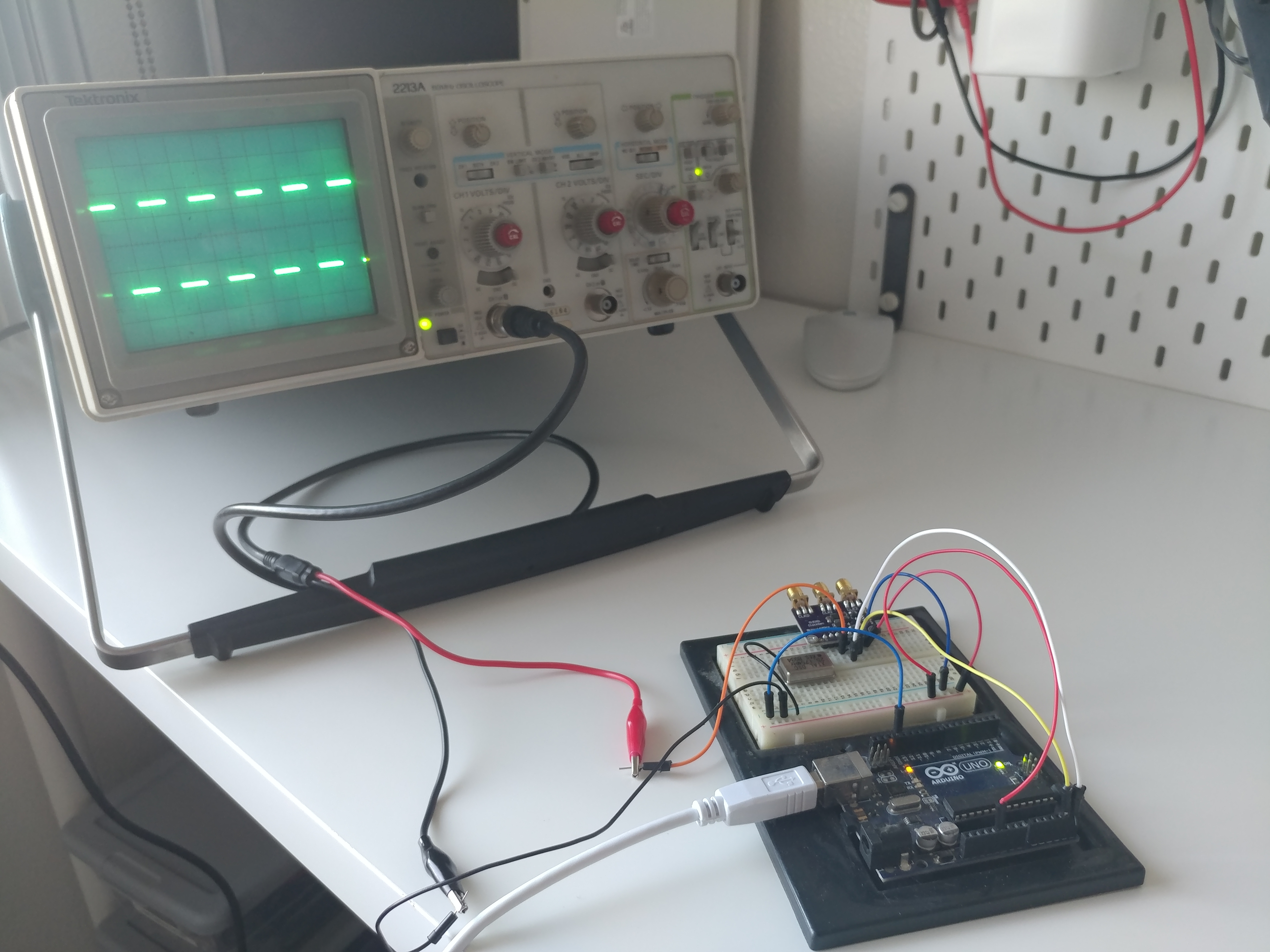
<p>Because I didn’t yet have a working breadboard layout, I designed my circuit around the ability to easily prototype rather than to make a final device. Thus, I wanted just the bare minimum of the 6502, 32K ROM, 8K RAM, the LCD pins, reset circuitry, a power header, and ample open databus connections to attach wires to. Additionally, I wanted to use an external clock source, since I still wasn’t entirely sure if the crystal I was using was even a good enough clock for the 6502. I had been doing some experimenting with an Arduino Uno controlling an I2C clock generator and that appeared to be much more stable than the crystal. Or, at the very least, I found the square waves to be much sharper even up to 25MHz:</p>

<p><img src="/assets/posts/arx6502/scoping.jpg" alt="Testing an I2C clock generator with an analog scope. Aesthetic." title="Classy scope there, buddy!" /></p>

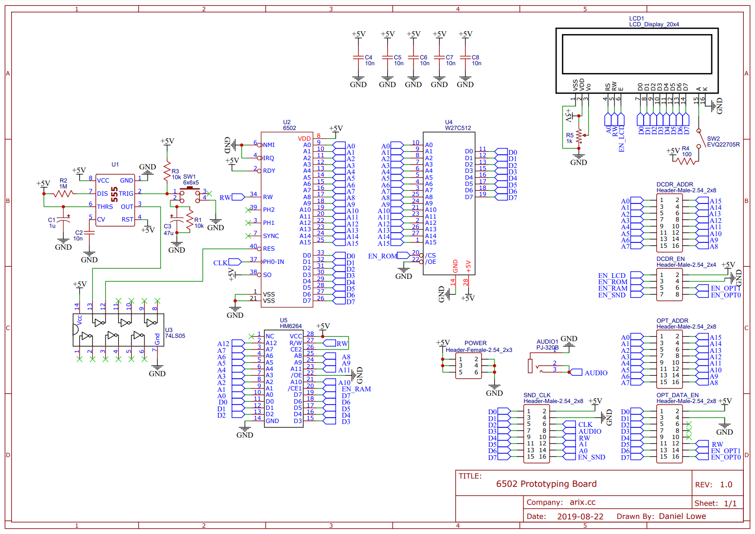
<p>Lastly, I also needed an address decoder. Because I was still figuring that out, I wanted that to be external as well. In any case, my needs were decided and I set out to create a schematic. I had heard good things about JLCPCB and EasyEDA from a friend, so I went with their software. It was, in fact, easy. I plopped the components I needed onto the schematic, connected each pin to a net, and that was that. Here’s what I came up with (<a href="/assets/posts/arx6502/Schematic.pdf" target="_blank">full pdf available</a>):</p>

<p><img src="/assets/posts/arx6502/Schematic.png" alt="Full system schematic." title="Full system schematic" /></p>

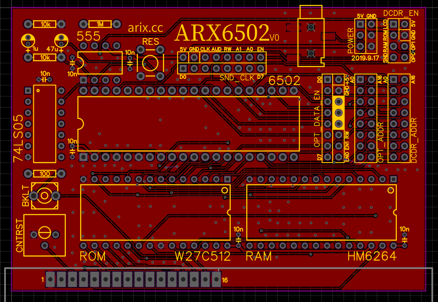
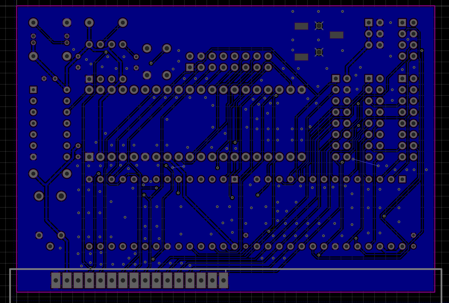
<p>It doesn’t look like much but I was pretty sure this was everything I needed, so, I began laying everything out on a PCB. It was a bit of a learning curve at first but I think I did an acceptable job for my first time. I hadn’t taken any formal EE classes at the time, pretty much all of my PCB knowledge was from watching Dave Jones at the EEVBlog. In any case, I came up with the following layout:</p>

<p><img src="/assets/posts/arx6502/board_top_layer.png" alt="Top layer of PCB." title="Top PCB layer" /></p>
<p class="img-caption">Top Layer</p>

<p><img src="/assets/posts/arx6502/board_bottom_layer.png" alt="Bottom layer of PCB." title="Bottom PCB layer" /></p>
<p class="img-caption">Bottom Layer</p>

<p>While I didn’t know much at the time, the two rules I remember following closely were to use plenty of ground-plane stitching as well as use as few right-angle traces as possible (prefer 45 degree or below). In any case, I ordered and populated the board!</p>

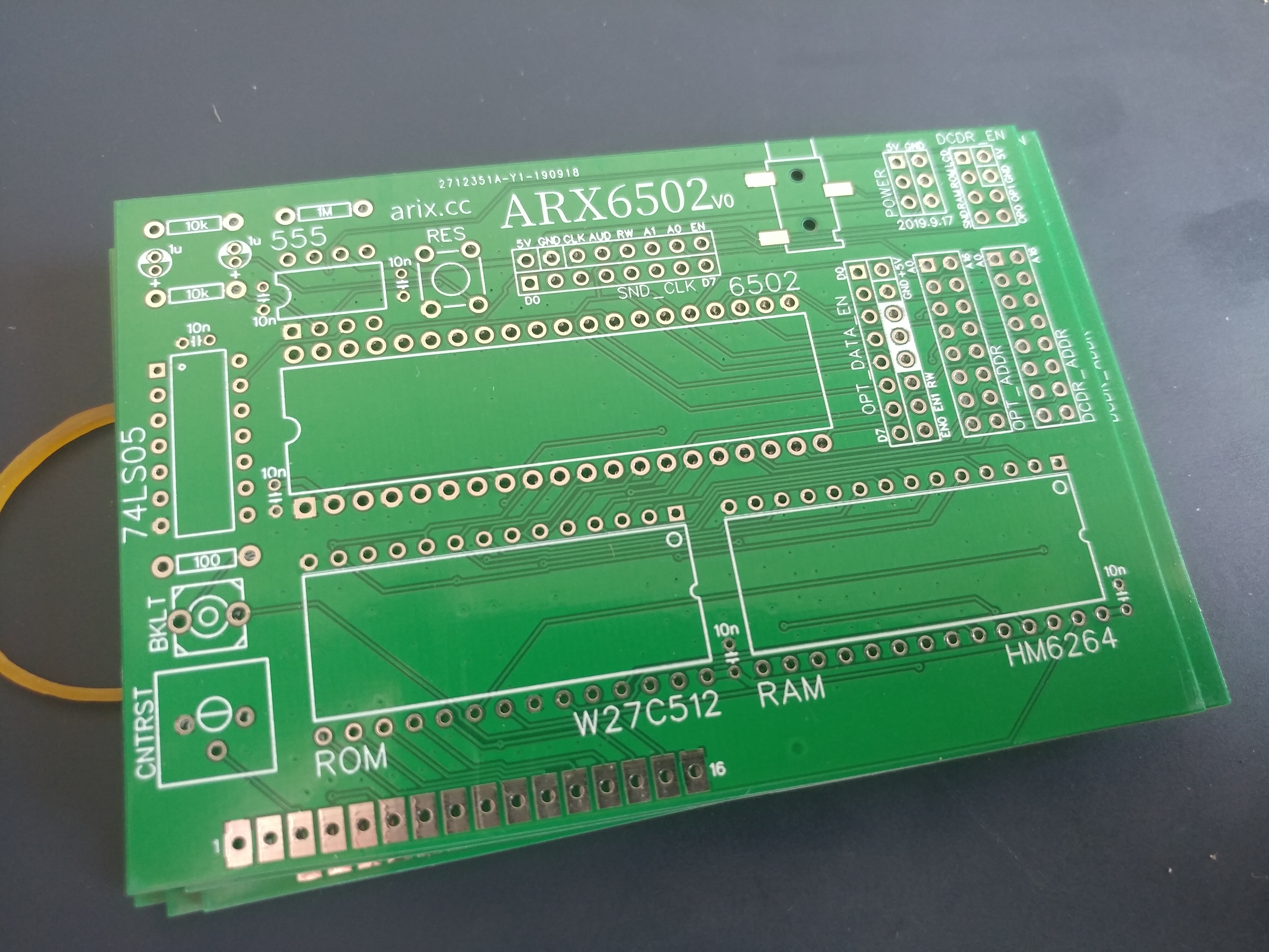
<p><img src="/assets/posts/arx6502/fresh_tasty_boards.jpg" alt="New boards arrived!" title="Fresh and tasty boards!" /></p>

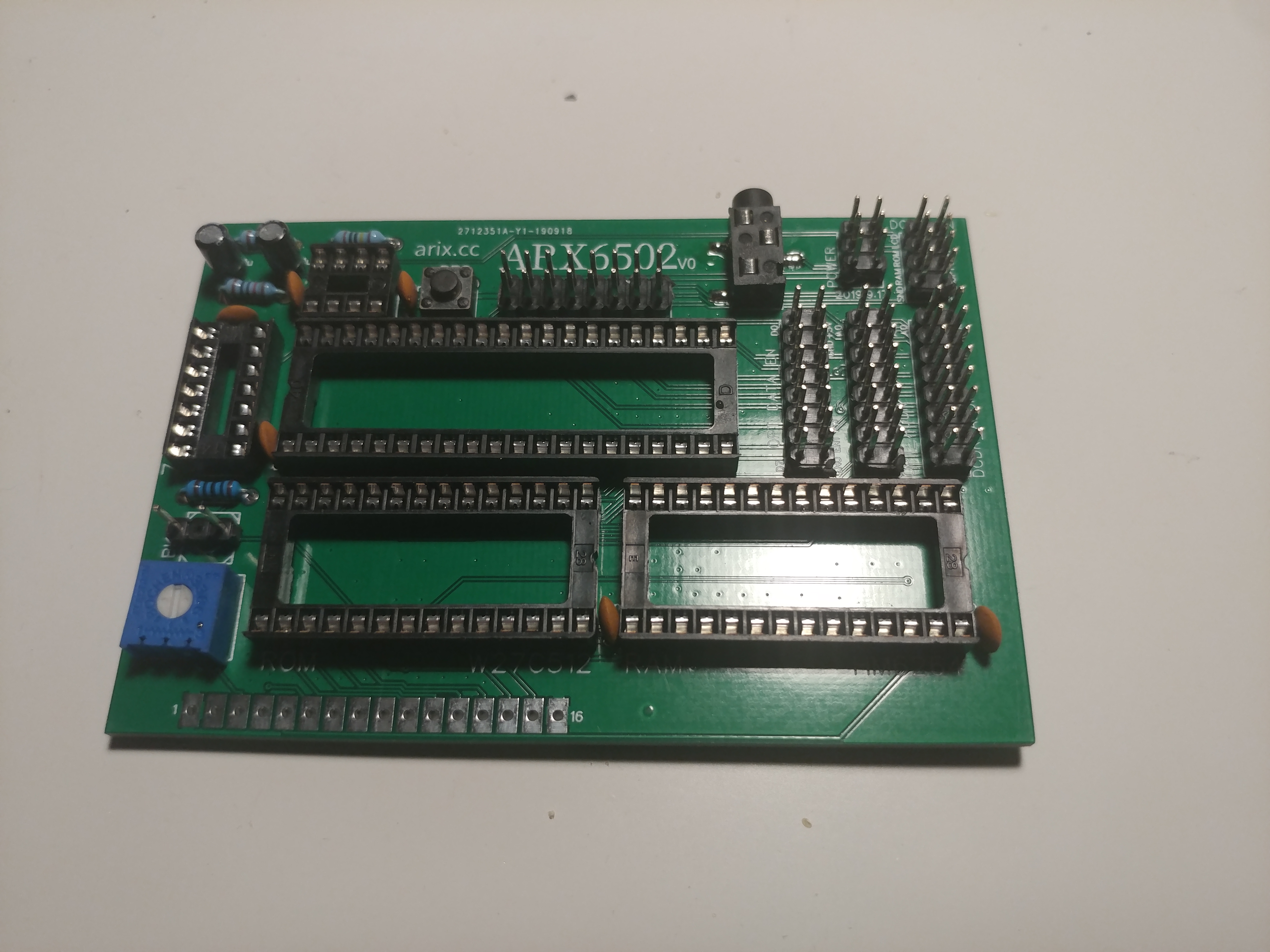
<p><img src="/assets/posts/arx6502/populated_board.jpg" alt="Board is populated with most components" title="Populated board" /></p>

<h2 id="testing">Testing</h2>

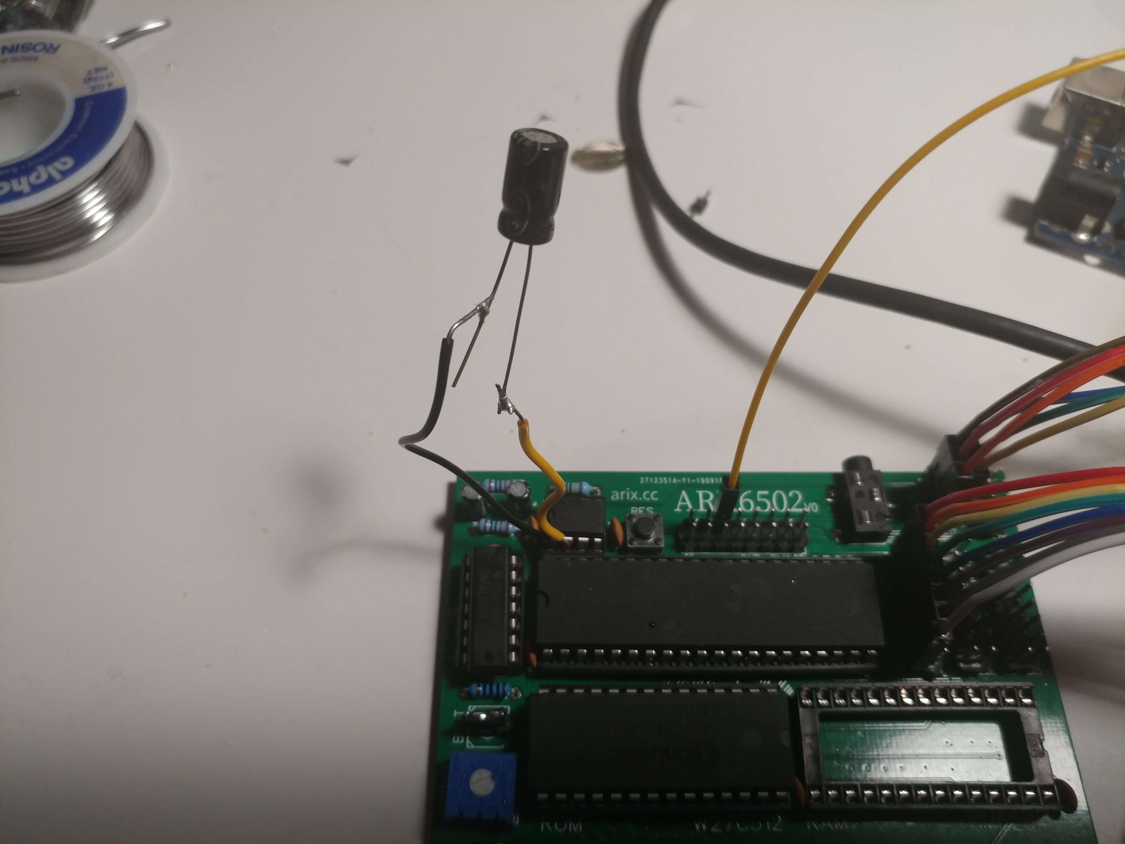
<p>Everything was fitting well so far. And, next, it was time to actually begin testing. The first section of my PCB I had trouble with was the reset circuitry. I was using a 555 timer with some capacitors, resistors, and a NOT gate to invert and trigger the active-low reset pin on the CPU. For whatever reason, it only worked sometimes, and I eventually realized this was a matter of it triggering too quickly, so I used a larger value of capacitor than planned. The testing, though, looked a <em>bit</em> ugly…</p>

<p><img src="/assets/posts/arx6502/bigboycap.jpg" alt="Large capacitor hanging off of the board" title="He's just hangin' in there..." /></p>

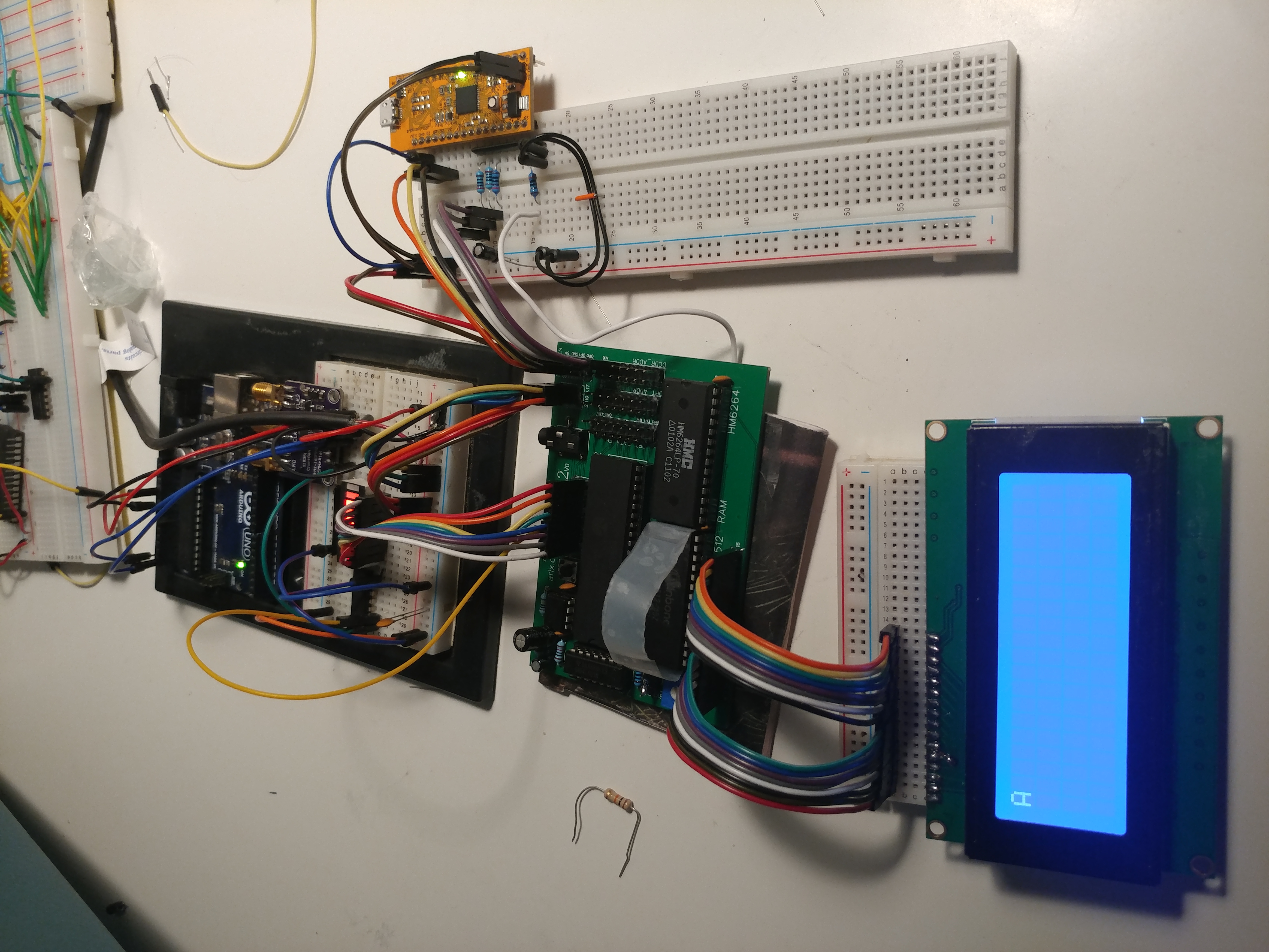
<p>Oh well, I thought, this is why I wanted a prototype board before trying to design a final one. Aside from that, everything went amazingly smoothly. I used the assembly code I had written for the breadboard test to try to test this version, and…</p>

<p><img src="/assets/posts/arx6502/first_success.jpg" alt="Success! A letter 'A' is displayed on the LCD." title="Success!" /></p>

<p>It worked!! I was able to initialize the LCD and output an ‘A’ character. I should note, I’m skipping over a lot of other development I needed to get here. For example, on the right is an FPGA that I programmed using ICEStudio to do all the address decoding. It’s meant to take the 6502’s address as an input, and output an enable signal to the LCD when it matches a certain value. This would normally be the job of the PLA on a Commodore 64, for example (or discrete TTL on even older machines).</p>

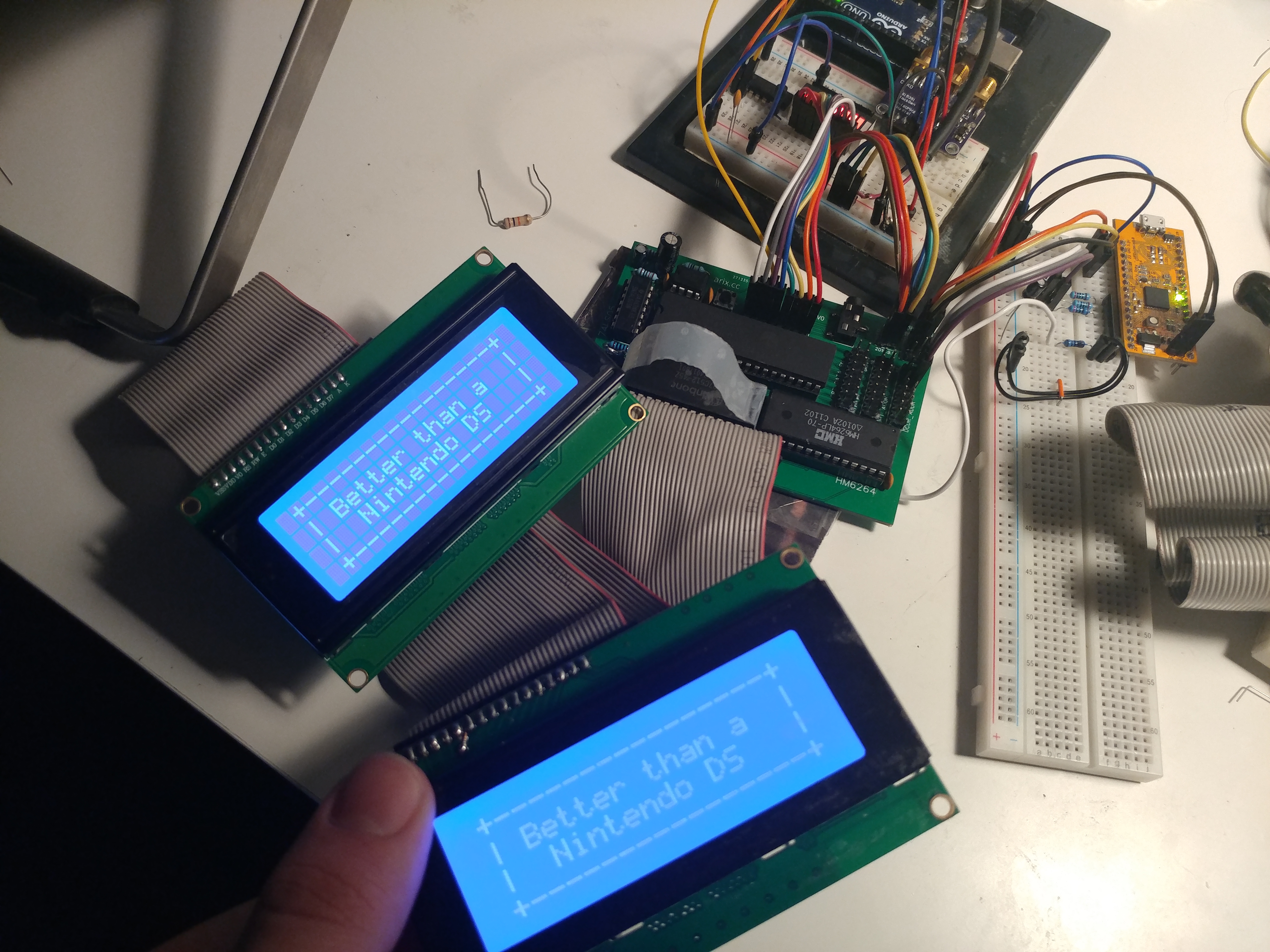
<p>With that much working, I didn’t stop there. I wanted to test even more of what I could do. For no reason at all (truly, for no reason), I connected two screens and added a little bit more significant output. <a href="/assets/posts/arx6502/LCD.txt" target="_blank">Here’s a link to the assembly code used here</a>, if you’re so inclined.</p>

<p><img src="/assets/posts/arx6502/ds.jpg" alt="The same text is displayed on two screens at once." title="I'm not so sure it is, after all..." /></p>

<p>Silliness and jokes aside, my next step was to get some form of input working. I was hoping to use a PS/2 keyboard, but after reading the documentation for it, I didn’t have the components needed. So, I went a little bit simpler. I wired up 6 buttons to a tri-state buffer and added another line from the FPGA address decoder to enable the buffer at a different address than the LCD. And, after wiring the buffer to the databus, I was able to read from them! As before, <a href="/assets/posts/arx6502/Input.txt" target="_blank">here is the assembly code for this test as well</a>.</p>

<iframe width="560" height="315" src="https://www.youtube.com/embed/x1-gdR8Q0p8" title="YouTube video player" frameborder="0" allow="accelerometer; autoplay; clipboard-write; encrypted-media; gyroscope; picture-in-picture" allowfullscreen=""></iframe>

<p>You’ll note that I also took a little bit of time to clean up the wiring here and minimize as I was working. After this point, I ran out of time and ideas and didn’t end up continuing the project any further. Now that I’m just about to graduate though, I’m definitely considering working on this some more and hopefully making a board that has everything I need, possibly even a controller? A gameboy-like system would be pretty neat! In any case, that’s all I have to show, thanks for reading!</p>]]></content><author><name></name></author><category term="hardware" /><category term="featured" /><category term="pcb" /><category term="retro" /><summary type="html"><![CDATA[After watching several repair videos about Commodore 64s, Nintendos, and other 8-bit era computers, I came to the conclusion that it can’t be that hard to make one, right? Here’s my process from concept to prototype!]]></summary></entry></feed>